Idea
We wanted to create the world’s smallest brushless dc (BLDC) quadcopter.
Nowadays there are tons of quadcopters and they all share the same problem: they are too big and heavy.
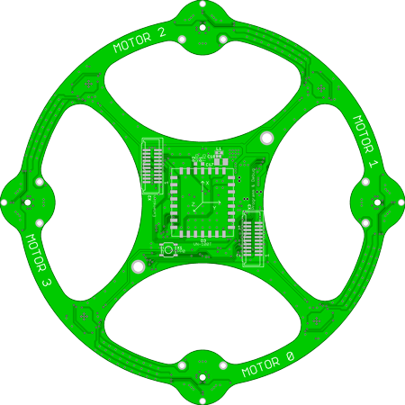
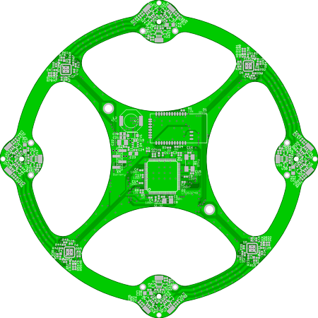
So the Idea was to create a quadcopter out of a single PCB holding all the electronics and of course also the motors.
Features
- Main CPU Arm Coretex M3
- 4 x sensor less BLDC driver AVR based
- Integrated 9DOF IMU by Vectornav
- Controllable by Bluetooth.
- Joystick
- Windows Software
- Everything on a single PCB
- Extension connectors
Special Thanks
First of all we would like to thank the “University of Applied Sciences Upper Austria” for the excellent cooperation!
Special thanks go to:
- FH-Prof. DI Dr. Markus Pfaff for supervising the project
- Dipl.-Ing. Dr. Martin Staudecker for the support with the drone model identification
- Dipl.-Ing.Dr.techn. Helmut Ennsbrunner for general guidance in controller design
- Armin Brandl for processing our purchase orders so fast

Demonstration
Overview
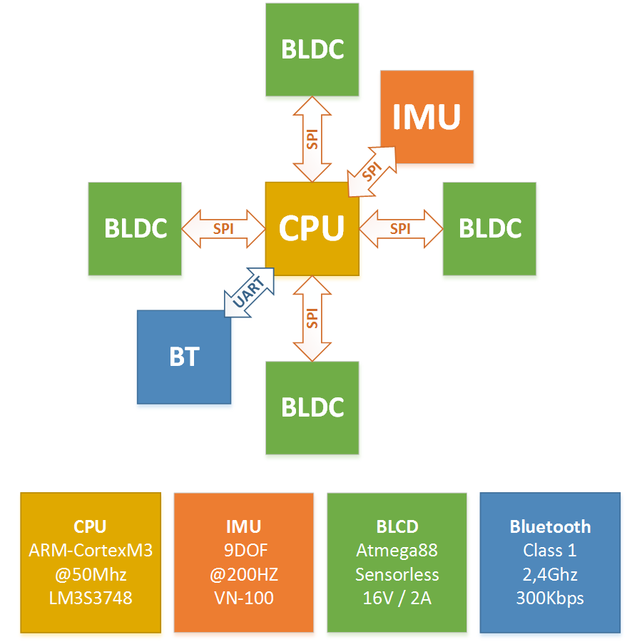
CPU
As main CPU we used a powerful Cortex M3 ARM CPU, that has been clocked with 50MHz.
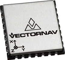
IMU

The IMU, or better to say the AHRS that has been used was a VN100 from the US company Vectornav. We decided to use this sensor, because it already handles the sensor fusion and Kalman filtering. The sensor module includes:
- Magnetometer (3 axis)
- Accelerometer (3 axis)
- Gyroscope (3 axis)
- Kalmanfilter
- Autotuning and callibration
- Temperature calibration
BLDC
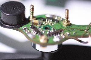
One of the trickiest and most time consuming parts of the entire project were the drivers for the 4 BLDC motors. BLDC motors need an extensive effort to work properly. The problem with this implementation of a brushless controller is the space limited environment. The only space that was left, was underneath the motors (for the driving stage) and between the motors on the outer ring (for the control stage). The brushless controllers are based on a ATmega168 combined with a powerfull 2A driving stage.
The BL-CPUs communicate with the main CPU using the SPI bus. This is done with high-speed to achieve mimimum dead time when controlling the motors from the main CPU.
Some key facts:
- 200Hz update rate
- digital SPI interface
- RPM monitoring
- 2 Status LEDs
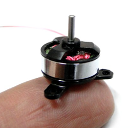
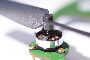
Brushless Motors
The brusless motors that have been used were the Hobbyking “AP03” motors in the 4000RPM/V edition. With the used propellers this motor provides a thrust of ~55g at a maximum current of 2A per motor with a maximum weight of 3.1g.
Bluetooth

To be able to communicate with the Joystick or even a smartphone a bluetooth 2.1 module has been implemented. This bluetooth module allowed us to achieve high bandwidth communication with the PC software and Matlab and also control-only communication with a Joystick. The range of bluetooth was enough for our application, as squadrone is designed for indoor flight only.
PCB Design
The PCB has been designed from ground up using the programm Cadsoft Eagle. It was assembled using reflow soldering combined with hand soldering.
Extensions
The possibility to connect expansion boards enables a wide range of upgrades, such as other wireless standards, sensors or other peripherals. The boards can be connected via the two 20-pin headers. These headers provide several communication interfaces to the main-processor, such as I2C or SPI.
The Bluetooth expansion board has been designed to make it possible to communicate wireless with a PC or the joystick.
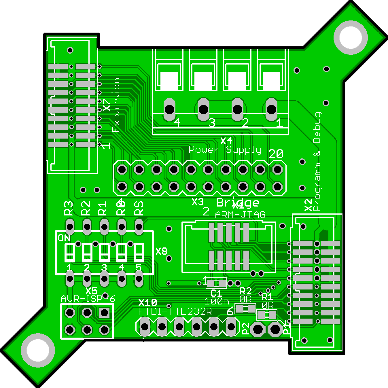
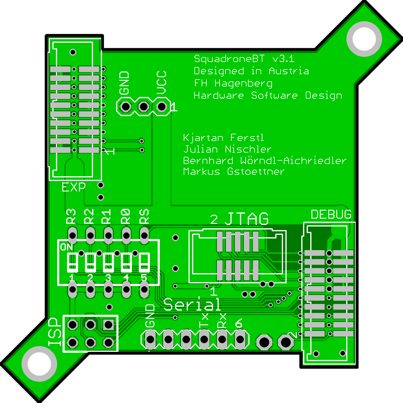
The Debug board makes it possible to power the quadcopter with an external power supply. This board can also be used to program the main-processor and the four motor controlling microcontrollers.
Joystick
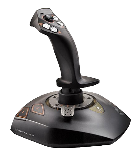
Based on a logitech wingman extreme digital 3d, we designed a wireless battery powered joystick to control the quadcopter.
The joystick has 11 buttons and 4 potentiometers measuring the X-, Y-, Z-axis and the throttle handle.
After turning the joystick on the communication mode can be set by pressing key D6. There are two communication modes available, the slave mode and the master mode. By default the master mode will be used. The difference between these modes is only, that in master mode the joystick searches for a quadcopter in range and connects to it and in slave mode the joystick accepts an incoming connection from e.g. a computer. The salve mode can be used as a debug interface or to analyze the packets.
When the connection has been established, the green LED signals this to the user. Now the motors of the quadcopter can be started by pressing D2. If the trigger is pulled now, the quadcopter increases the engine power and starts hovering. Now the control system is working and tries to keep the quadcopter stable. Moving the handle in X or Y direction lets the quadcopter also move into this direction. The throttle slider can be used to increase the height. When the trigger is released the quadcopter stops the control circuit. D3 disables the motors.
Hardware
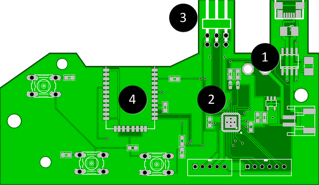
1. Power supply
The joystick can be powered with a USB-micro connector providing 5V. If a LiPo-battery is connected to the PCB, it will be charged. The charger-IC (MAX1811) is a standalone device, so it is possible to charge the battery without the need to power up the microcontroller. A low dropout regulator (LDO, TPS78233) converts the battery voltage, which is about 4.1V to 3.3V to supply the system. A status line from the charger to the microcontroller tells the microcontroller whether the battery is being charged or not.
2. Microcontroller
The main-processor is a ATmega168PA, providing 23 GPIOs, three timers and a 12-bit ADC. It operates at 8 MHz using the internal RC-oscillator. The internal 12-bit ADC is used to measure the potentiometer. By doing this the angles and the throttle position can be calculated. The communication with the Bluetooth module happens via UART.
3. Debug-Interface
To program the microcontroller we decided to use the ISP (in system programming) interface. This interface uses just 3 pins of the microcontroller, with the lack of a debugging capability.
4. Bluetooth Module
The Bluetooth module (RN-41) enables the communication to the quadcopter. It is qualified for Class 1 and Class 2.1 Bluetooth. The module can be configured via UART. When the connection has been established, the module will be switched to communication mode and acts as a serial interface connection.
Reading the handle peripherals
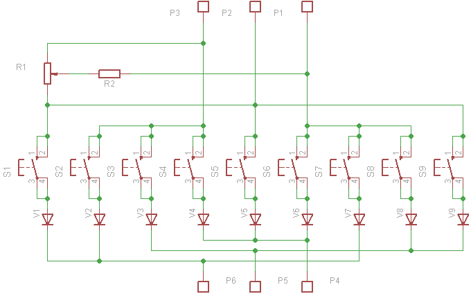
The top key and the Z-axis potentiometer have to be read from a matrix. The result after reverse-engineering the top PCB was following circuit:
Software
The Software was developed to test and debug the Drone in its developnment stage. It shows live charts with the IMU, engine and controller data and enables the user to capture a trace. Moreover it is possible to do various configurations on the Drone, such as setting the parameters of all Controllers.
Features

- Start / Stop the engines and the controllers
- Control the Drone with sliders or an USB Joystick
- Communicate over a serial or bluetooth
- Configure the PID controllers
- Live 3D view
- Live charts
- …
Serial port / Bluetooth
Windows provides a serial port when connecting bluetooth devices to the pc. The software can connect to bluetooth devices even without the manual connecting process, this simplifies the process and eliminates the manual input of the Bluetooth pin.
It is recommended to use the serial port instead of directly using the bluetooth implementation as the bluetooth stack often times out due to the lack of implementation in the Windows Bluetooth API.
A quadcopter is generally a very unstable system, that is very hard to control. The tricky parts are generally two things:
- Getting reliable sensor data is very hard
- The controller needs to be fast enough
Control
Aquiring usable sensor data
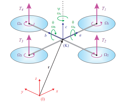
As the Quadcopter is floating in space, it has multiple degrees of freedom.
- 3 degrees of freedom for movement (x, y z)
- 3 degrees of freedom for rotation/angle(pitch, roll yaw)
In order to aquire all this data, a powerfull sensor system has to be used. In this case a system that uses 9 distinct sensor values which include:
- 3 axis accelerometer
- 3 axis gyroscope
- 3 axis magnetometer
The sensor we used is a Vectornav VN100 Altitude Heading Reference System (AHRS), this sensor module already implements all compensation algorithms, filters all sensor data and combines them into the current angle the sensor is heading.
Controlling
Controlling the quadcopter is almost as tricky as aquiring usefull sensor data. Our first approach was to control the motor PWM directly, by setting it according to the angle that has been received from the sensor. The problem with this “easy” approach where only one PID controller would have been used was that the system got too slow to react to changes. This resulted in a quadcopter that was not flyable.
Therefore we headed for a different more methodical approach. We started controlling the system from ground up – layer per layer.
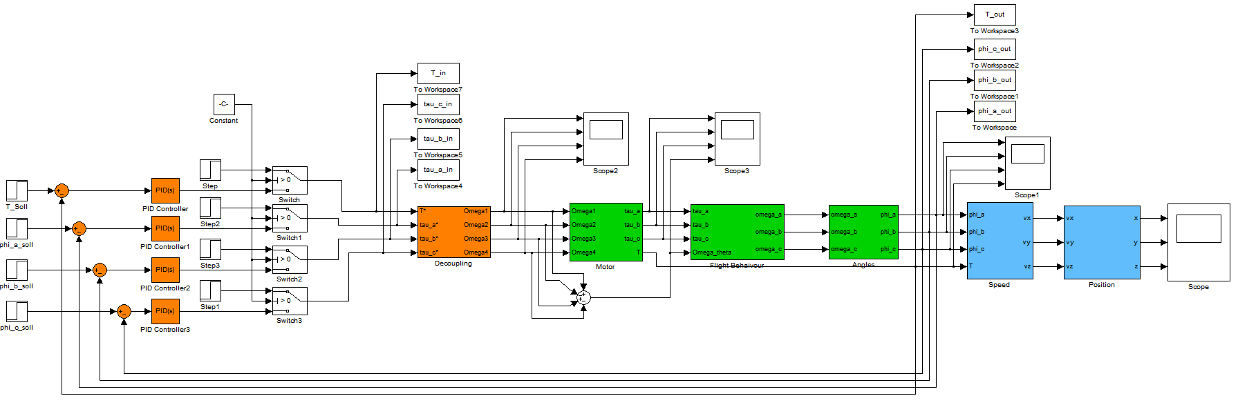
So we ended up with a multilayer cascading structure:
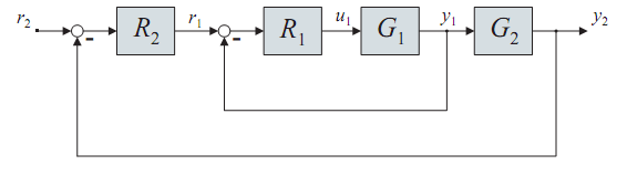
RPM controller
The first layer of control is the RPM controller of the brushless DC motors. The small ATmega processors on the outside of the quadcopter only do the basic commutation and the measurement of the current RPM values. As the brushless motors can rotate with up to 32000 RPM, the small 8 MHz clocked ATmega processor can’t do the actual control, so the RPM control has to be done from the main processor. To get an adequat transfer function of the motor and the PWM control a Matlab interface for the drone has been implemented. With this Matlab interface it was possible to do certain measurements for PWM vs. RPM, which allows to measure a precise transfer function of the brushless dc motors.
We ended up with a quite adequat transfer function for motor control:
Transfer function:
           5.363
z^(-2) * ----------
         z - 0.9575

Sampling time: 0.005
Using this transfer function – that is basically a PT1 with dead time, we were able to build a simple PI controller, that enabled fast and reliable control of the motor.
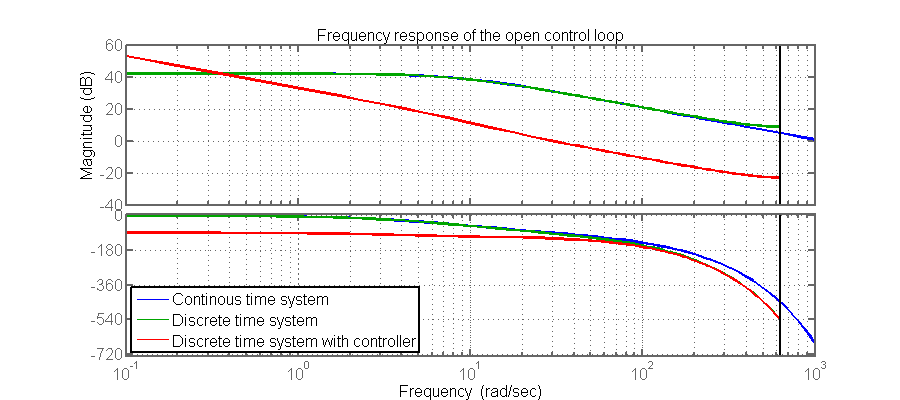
With an overshoot of maximum 10% and a desired regulation time of 50ms we ended up with a discrete time PI controller with the following parameters:
Transfer function:
0.02677 z - 0.02498
-------------------
       z - 1

Sampling time: 0.005

Kp =

    0.0268

Ki =

    0.3569
Which leads to the following frequency response of the open controll loop of the RPM controller:
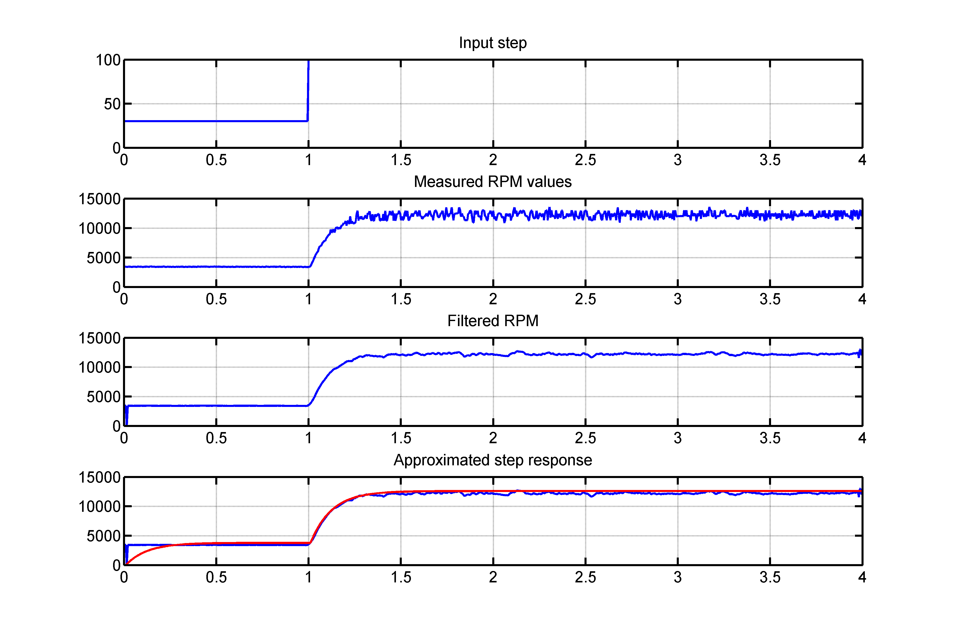
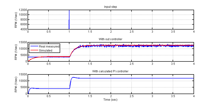
Using this regulator resulted to a fairly stable RPM regulation. The simulation results were really close to the actually measured results. The following step response compares the unregulated system with the controlled system.
Rotation speed controller
The next controller on top of the RPM controller is the “OmegaController”, this controller tries to regulate the rotation speed (the change of the angle the quadcopter is heading). This controller gets it’s data directly from the gyroscope on the VN100 sensor module. This gives us a very stable control of the flight of the quadcopter, as there is no need to wait for the angle data from the sensor module (would be additional dead time). With rotation speed controller enabled, the quadcopter ist stable in air, at a certain angle, so it tries to hold the quadcopter by minimizing the rotational movement.
All measurements have been done by tieing the quadcopter to a string, and let it rotate in open space – this resulted in the following step response:
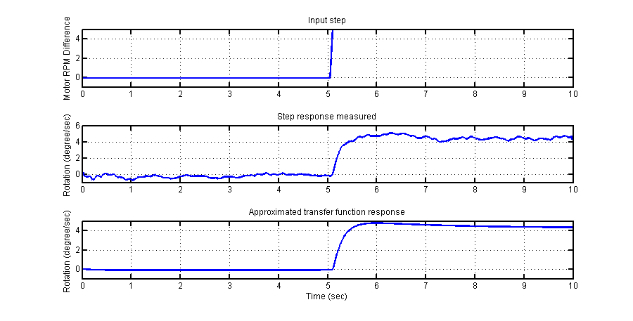
The approximation of this transfer function resulted in a system of third order.
Transfer function:
           1.842 s + 0.8582
---------------------------------------
0.0007561 s^3 + 0.3641 s^2 + 2.01 s + 1
Designing a controller for this wouldn’t be too hard, but there was one massiv problem. An integration was not possible!
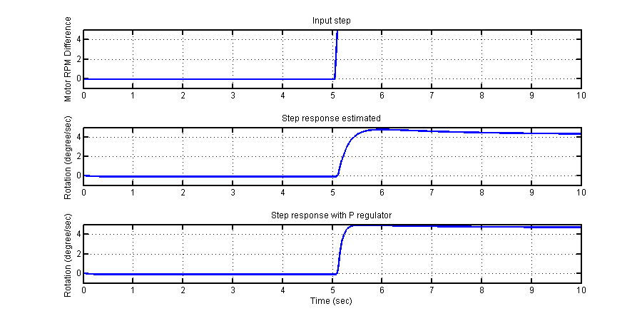
The sensor data is sampled using a discrete time sensor (so only one value at a time is sampled) – this has the massiv downside that integration may lead to a continous error as the mean of the sensor values drift due to measurement and sampling inaccuracy. This only allowed us to implement a simple P controller. (KP = 2500)
Implementing this controller we ended up with the following step response:
Angle controller
The next and final step for a flyable quadcopter is the angle controller. This angle controller is designed to hold the quadcopter horizontal.
For this controller the caculated angle data from the AHRS sensor is used – this data acts as horizon to which the drone can be controlled to. As with the rotation speed controller an integration is not really possible, as sensor drifts are problematic.
The parameters for this controller were hard to measure (step response is not possible) as the system is completely unstable without controller.
Therefore an approximation according to Ziegler & Nichols has been used. This involved:
- Implementing a P-Controller
- Incrementing the P value till the system gets at the edge of stability
- Use 1/2 of P to get a stable system
After implementing this controller the quadcopter was stable in mid air.
Communication
This article is about the communication between the drone and various peripherals for debugging, testing and of course flying. Currently the drone can communicate with the wireless joystick and with the PC software (wired and wireless)
Requirements
| CableIt has to work over a cable to reduce the number of problems that may occur when testing and developing. | RadioIt has to work in the air to control the drone in flight mode. |
| ProtocolWe need a definition how the data is transmitted in to read it at the receivers side. | SafetyData loss can be fatal for the drone, it could misread a command and responde with any random reaction. |
The commands and data sent are packed in a previously self developed command&data packaging protocol which includes a checksum for data integrity. Once packed in this protocol the frame is once more wrapped to determine the beginning and the end of a packet, this is done with the Serial Line Internet Protocol (SLIP).
Data Package
| Data byte | Description |
|---|---|
| HIGH(ID) | Each command has an incremental ID to determine Package loss. |
| LOW(ID) | |
| Command | The command identifier. |
| Data length | The length of the data transmitted in this package. |
| Data … | The actual data, ammount of bytes can vary depending on the data length given before. |
| HIGH(CRC) | Checksum over all bytes, without the checksum itself, from the high byte of the ID to the last data byte. The checksum is calculated by the CRC-CCITT (CRC-16) algorithm. |
| LOW(CRC) |
For the table above, the first transmitted byte is the height byte of the package id. The general byte order when sending data is big-ending, while the bit order is LSB first as most serial ports work by default.
Framing (SLIP)
The Serial Line Internet Protocol (SLIP) is defined for IP to determine a package begin and ending when transmitting over a serial line. It provides minimal overhead and allows an easy algorithm to decode the data, so it fits our application perfectly.
It uses an end character (0xC0) and escape character (0xDB) to escape the and end character if it occurs in the data segment.
Example
Input frame:
| … | … | 0xC0 | … | … | 0xDB | … |
Converts to:
| … | … | 0xDB | 0xDC | … | .. | 0xDB | 0xDD | … | … | 0xC0 |
For further documentation on the serial line internet protocol framing, see http://www.ietf.org/rfc/rfc1055.txt
Implementation
Both, the packaging and the SLIP framing was implemented in C previously, named XSie, and has been ported to C# for the PC Software.
For compatibility purpose of further equipment it is recommended to receive the data with a baudrate of 115200 baud. The baud rate does not change the actual baud rate over bluetooth, so even when the baud rate is the same data it can be transceived but in order to keep up with the data sent from the drone the baud rate should not be lower than 115200 baud for further peripherals.